


Choosing the top Quick Connect Couplers requires more than comparing catalog prices. These small components control fluid transfer, maintenance speed, and equipment uptime. A coupler may look ordinary on a workshop bench. Under pressure, however, seal quality, connection force, and contamination control become decisive.
Industry data supports this practical view. The Grand View Research Hydraulic Equipment Market Report identifies construction, agriculture, and industrial machinery as major demand sectors for hydraulic components. The MarketsandMarkets Hydraulic Equipment Market analysis also highlights automation, mobile machinery, and preventive maintenance as important growth influences. These findings suggest a useful selection principle: the best coupler must match the machine’s working environment, not merely its advertised flow rate. Reports from the International Fluid Power Society further emphasize correct sizing, cleanliness, and pressure management. Those details matter when an operator connects a dusty excavator line with gloved hands.
This guide compares leading Quick Connect Couplers through pressure capacity, flow efficiency, sealing performance, interchangeability, corrosion resistance, and service life. It also considers ISO 7241 compatibility, because appearance alone cannot confirm safe interchangeability. Some manufacturers publish extensive test data. Others provide limited field evidence. That difference deserves attention. No universal winner exists. A coupler suitable for a compact loader may restrict flow on a high-cycle press. Likewise, a low-cost model may create hidden expenses through leakage, downtime, or difficult maintenance. The final ranking therefore combines manufacturer specifications, recognized standards, practical service experience, and independent market evidence. It remains an informed comparison, not an absolute verdict. Real operating conditions can still change the result.
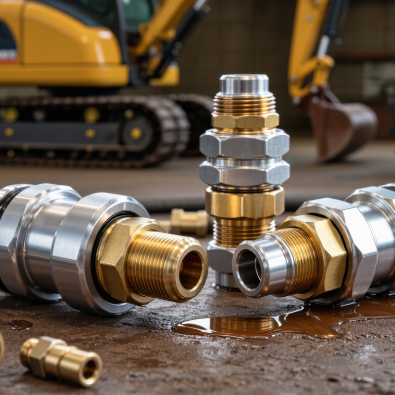
Quick connect couplers join hydraulic lines without complex tools. They contain mating halves, valves, seals, and a locking mechanism. When disconnected, internal valves help limit fluid loss and dirt entry. However, no coupler is ideal for every machine.
The main ISO 7241 categories are Series A and Series B. Series A couplers are common in agricultural and general hydraulic equipment. Series B couplers suit many industrial and mobile applications. Their profiles are not automatically interchangeable. Check the full standard, size, pressure rating, and connection method before choosing. Threaded, push-to-connect, and sleeve-lock designs behave differently under vibration.
Flat-face couplers are another practical type, although many follow standards outside ISO 7241. They reduce exposed fluid and are easier to wipe clean. This matters near dusty loaders or outdoor equipment. During service inspections, look for damaged seals, rounded locking balls, and difficult sleeve movement. A coupler that connects roughly may signal trapped pressure, contamination, or misalignment. Do not force it.
Material and seal selection also need attention. Steel handles demanding pressure, while stainless steel can improve corrosion resistance. Seal compounds must match the hydraulic fluid, temperature, and operating cycle. Pressure ratings can change with size and temperature. That detail is easy to miss. The best coupler is therefore the one whose ISO 7241 series, dimensions, flow capacity, and maintenance requirements match the actual circuit, not merely the highest-rated option.
The top quick connect couplers are not chosen by pressure ratings alone. They must match pressure, flow, temperature, and leak-control requirements. ISO 7241 provides dimensional and performance guidance for hydraulic quick-action couplings, while ISO 16028 addresses flat-face designs used in contamination-sensitive systems.
Pressure ratings need a safety margin above normal operating pressure. A coupler rated for 250 bar may perform poorly near that limit, especially during pressure spikes. Flow testing matters just as much. A small internal passage can create noticeable pressure loss, heat, and slower actuator movement. Measure flow with the hose, fittings, and coupler connected. Catalog figures can look better than field results.
Temperature changes seals and materials. Check both continuous and peak temperatures, including hot oil after long cycles. Leak control also deserves closer attention. The U.S. Department of Energy reports that compressed-air leaks can waste 20–30% of compressor output. That figure makes shut-off valves, reliable seals, and clean connection faces practical priorities. ISO 4414 also emphasizes safe pneumatic energy control. A coupler that drips after disconnection is not truly efficient. Small leaks matter.
In real installations, dust on a coupler face can defeat an excellent design. I have seen maintenance teams trust ratings without checking pulse cycles or hose bending. That is an easy mistake. Verify pressure drop, temperature exposure, connection frequency, and leakage after installation. Performance data should come from the complete assembly, not one isolated component.
ISO 16028 flat-face couplers suit demanding hydraulic systems with frequent connections. Their flush valves reduce trapped air, fluid loss, and contamination during service. In practical field work, this matters when hoses are changed beside dusty excavators or compact loaders. The coupler must match the circuit, not merely the hose diameter. Many models support working pressures between 250 and 420 bar, but pressure ratings vary by size, temperature, and connection method.
According to MarketsandMarkets’ 2024 Hydraulic Equipment Market report, the global market is projected to grow from about USD 44 billion in 2024 to nearly USD 56 billion by 2029. That expansion reflects continued demand for reliable mobile and industrial hydraulics. ISO 16028 designs help maintenance teams reduce cleaning time and protect sensitive valves. Their flat surfaces are easier to wipe before connection. Small details matter.
Selection still requires careful checking. Compare rated flow, pressure drop, impulse performance, sealing materials, and connection force. A coupler rated at 420 bar may create excessive restriction at high flow. This is often overlooked. Temperature can also change seal behavior and leakage risk. The ISO standard improves dimensional compatibility, but it does not guarantee equal performance across every application. Field testing remains necessary, especially where shock loads, vibration, or repeated hot connections are expected.
For typical 7–10 bar pneumatic systems, the best quick connect coupler starts with the correct ISO 6150 profile. Profiles A, B, and C use different plug shapes and connection details. They are not automatically interchangeable. In workshop installations, a matching profile often prevents leaks, difficult releases, and unexpected flow loss. Check the working pressure, peak pressure, port size, and required airflow before choosing. A coupler rated above the system’s normal pressure gives useful safety margin.
Material also matters. Steel suits demanding workshop use, while treated aluminium reduces weight. Seals must match the air quality, temperature, and cleaning products. For dusty areas, a protective cap helps keep particles away from the valve. High-flow designs can reduce pressure drop, but they may feel bulkier in compact tools. Selection is rarely perfect on the first attempt. I have seen operators choose a smaller coupler for convenience, then lose tool performance at the trigger. The datasheet remains essential, because profile names alone do not reveal actual flow capacity.
What Are the Top Quick Connect Couplers?
Selecting a quick connect coupler starts with size, not appearance. Match the port thread, hose bore, and required flow rate. A coupler that fits the hose can still restrict airflow or fluid movement. Measure the connection instead of relying on memory. Small details matter. In field maintenance, a slightly undersized passage can create pressure loss, heat, and slower tool performance.
The media determines the seal and body materials. Air, water, oil, chemicals, and aggressive cleaning fluids require different resistance levels. Check operating pressure, temperature, and pressure spikes during startup. Safety features also deserve close attention. Choose sleeves that reduce accidental disconnection, and confirm whether the design allows connection under residual pressure. Never assume two couplers are compatible because their shapes look similar.
Cycle life depends on use, contamination, and handling. Frequent reconnecting needs durable valves and replaceable seals. Keep dirt away from open ends. Inspect wear patterns around the locking balls and seal area. Compatibility includes thread standards, valve style, flow direction, and dimensional clearance. A common mistake is selecting by maximum pressure alone. That rating may ignore vibration, pulsing, or frequent cycling. Test the complete assembly under realistic conditions before approving it. I would also question catalog claims when test methods are unclear. Reliable selection comes from matching specifications with actual operating habits.
| Coupler Type | Typical Nominal Sizes | Common Media | Typical Working Pressure | Typical Temperature Range | Safety and Shut-Off Features | Typical Cycle Life | Compatibility and Selection Notes |
|---|---|---|---|---|---|---|---|
| General-purpose pneumatic Poppet-style plug and socket | 1/4, 3/8, and 1/2 in nominal ports | Compressed air and inert gases | Commonly 7–15 bar (100–220 psi) | Approximately −20 to 100°C (−4 to 212°F), depending on seals | Manual sleeve locking; some designs include a pressure-relieving sleeve or safety lock to reduce accidental disconnection. | About 50,000–100,000 connection cycles in clean, properly lubricated service | Select the exact plug profile and thread standard. Similar-looking pneumatic profiles are not automatically interchangeable. |
| High-flow pneumatic Large-bore industrial coupler | 3/8, 1/2, and 3/4 in nominal ports | Compressed air, nitrogen, and other compatible gases | Commonly 7–12 bar (100–175 psi) | Approximately −20 to 100°C (−4 to 212°F) | Sleeve guard, locking balls, and optional automatic shut-off valves; flow should be isolated before disconnecting when required by the application. | About 30,000–75,000 cycles, strongly influenced by contamination and side loading | Best for tools and circuits requiring lower pressure drop. Match both the coupling series and the flow capacity, not port size alone. |
| Hydraulic ISO 7241 Poppet-style industrial hydraulic coupler | 1/4, 3/8, 1/2, 3/4, and 1 in nominal sizes | Mineral hydraulic oil and other approved hydraulic fluids | Commonly 210–350 bar (3,000–5,000 psi); size and design dependent | Approximately −25 to 100°C (−13 to 212°F), seal dependent | Sleeve locking, locking balls, and valve poppets. Do not disconnect a pressurized hydraulic line unless the coupler is specifically rated for that procedure. | Approximately 10,000–30,000 cycles under controlled laboratory conditions | ISO 7241 Type A and Type B profiles are different. Confirm the type, pressure rating, seal material, and thread or port connection. |
| Flat-face hydraulic ISO 16028-style coupler | 1/4, 3/8, 1/2, 3/4, and 1 in nominal sizes | Hydraulic oil, water-glycol fluids, and selected biodegradable fluids | Commonly 250–450 bar (3,600–6,500 psi), depending on size and series | Approximately −25 to 100°C (−13 to 212°F), depending on elastomers | Flat mating faces reduce fluid loss and air inclusion. Sleeve locking and visual engagement indicators are commonly available. | Approximately 5,000–20,000 cycles, with face wear and contamination being major factors | A strong choice for mobile equipment and hydraulic attachments. Flat-face profiles from different series may not mate safely even when dimensions appear similar. |
| Dry-break fluid coupler Double shut-off design | 1/4, 3/8, 1/2, 3/4, and 1 in nominal sizes | Fuels, solvents, chemicals, oils, coolants, and process fluids | Commonly 5–25 bar (75–360 psi); product-specific | Approximately −20 to 150°C (−4 to 302°F), depending on body and seal materials | Both halves close automatically when disconnected. Keyed or coded designs can prevent connection to an incorrect circuit. | Approximately 1,000–10,000 cycles, depending on media, cleanliness, and seal wear | Specify chemical compatibility, allowable leakage, vapor control, flow rate, and electrical continuity requirements. Verify hose and seal compatibility. |
| Cam-and-groove coupler Lever-operated hose connection | 1/2, 3/4, 1, 1 1/2, 2, 3, and 4 in nominal sizes | Water, fuels, oils, agricultural chemicals, powders, and dry bulk materials | Commonly up to 10–16 bar (150–230 psi); size and material dependent | Approximately −20 to 100°C (−4 to 212°F), with higher temperatures possible using suitable materials | Cam arms provide fast manual connection. Safety pins, locking clips, or guarded arms may be needed to prevent accidental opening. | Approximately 1,000–5,000 cycles in hose-transfer service | Not intended for connection or disconnection under pressure. Confirm coupling material, gasket type, cam-arm geometry, and application-specific standard. |
| Multi-coupling plate Multiple-line hydraulic or pneumatic connection | Typically 2–12 circuits; individual circuits commonly 1/4–1/2 in | Hydraulic oil, compressed air, coolant, and electrical or control lines | Commonly 100–350 bar (1,450–5,000 psi) for hydraulic circuits | Approximately −20 to 100°C (−4 to 212°F), depending on modules and seals | Guided alignment, locking handles, selective keying, and optional connection-status indicators help prevent cross-connection. | Approximately 5,000–20,000 cycles, depending on alignment and mating force | Useful where several lines must be connected simultaneously. Check circuit sequence, trapped pressure, mounting alignment, and interchangeability of each insert. |
| Thermal-management coupler Coolant quick disconnect | Commonly 1/4, 3/8, and 1/2 in nominal ports | Water, water-glycol coolant, dielectric fluids, and selected heat-transfer fluids | Commonly 3–16 bar (45–230 psi) | Approximately −20 to 120°C (−4 to 248°F), depending on fluid and seal material | Shut-off valves limit coolant spillage. Color coding, keying, and locking sleeves can help prevent incorrect connections. | Approximately 1,000–10,000 cycles, depending on cleanliness and thermal cycling | Evaluate internal volume, pressure drop, leak rate, galvanic compatibility, and coolant chemistry. Low restriction is important in high-flow cooling loops. |
| Electrical quick disconnect Connector with mechanical coupling | Contact configurations from 2 to 50+ contacts; wire size varies by design | Electrical power, signal, sensor, and control circuits | Electrical ratings commonly 30–600 V and 1–100 A per contact, depending on contact size | Approximately −40 to 125°C (−40 to 257°F), depending on housing and insulation | Latching, locking, keying, touch-safe contacts, and IP-rated sealing may be available. De-energize circuits when required. | Approximately 500–10,000 mating cycles | Match pin count, voltage, current, contact plating, environmental rating, cable diameter, shielding, and keying. Do not rely on physical fit alone. |