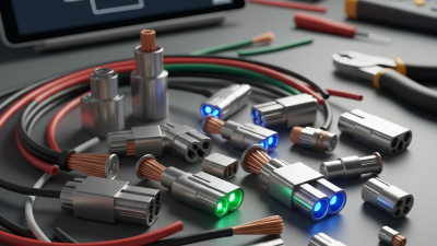
Choosing the right wire connector is rarely a simple catalog decision. Global buyers compare electrical performance, installation speed, material quality, and long-term reliability. A connector that works well in a dry control cabinet may fail in a humid outdoor junction box. Small details matter, including insulation thickness, contact pressure, locking strength, and resistance to vibration.
Dr. Paul G. Slade, a recognized authority on electrical contacts, has emphasized that “a connector is only as reliable as its contact interface.” This principle gives the wire connector market a practical direction. Housing design attracts attention, but the metal contact carries the real responsibility. Poor plating, loose crimping, or mismatched wire sizes can create heat at the connection point. That heat may remain invisible during initial testing.
This guide examines ten widely used wire connector types for international purchasing teams. It considers terminal blocks, crimp connectors, twist-on connectors, push-in connectors, lever connectors, waterproof connectors, ring terminals, butt connectors, quick-disconnect terminals, and modular connector systems. Each type serves a different working condition.
The ranking is not absolute. A compact push-in connector may be ideal for factory wiring, yet unsuitable for high-vibration machinery. A waterproof connector may protect an outdoor sensor, but increase cost and assembly time. That trade-off deserves closer attention.
Experience from installation sites, product datasheets, and verification testing should guide final selection. Buyers should also confirm wire range, temperature rating, ingress protection, certifications, and supplier consistency. Mistakes happen, even with experienced teams. Careful comparison reduces them.
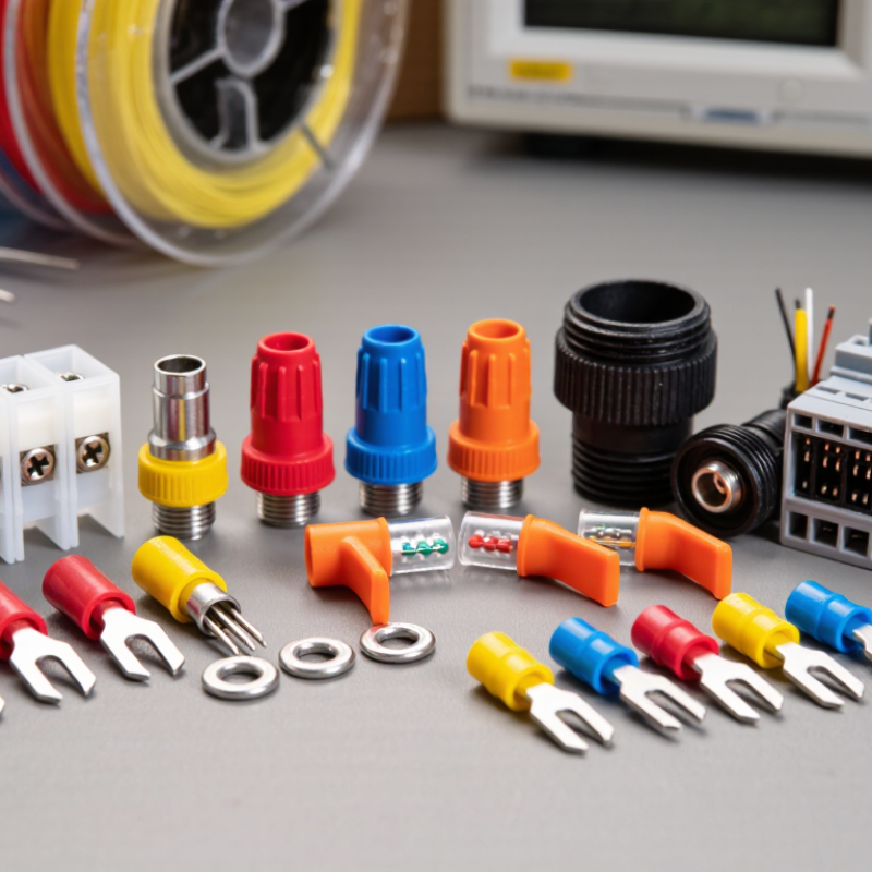
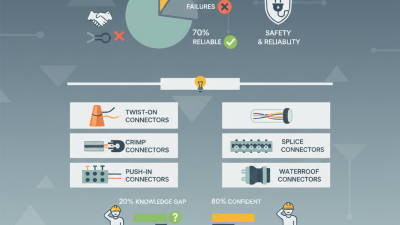
Global buyers usually compare ten wire connector types by installation speed, contact stability, and environmental resistance. Terminal blocks suit control panels, where labeled screw points simplify inspection and maintenance. Wire nuts work well for enclosed residential splices, but matching size and conductor type remains essential. Push-in connectors provide fast, tool-free installation for solid wires. Lever connectors accept several conductor types and allow visual rechecking. Crimp connectors create compact joints when the terminal, wire gauge, and crimp profile match precisely.
The remaining five include butt splice connectors, ring terminals, fork terminals, quick-disconnect terminals, and heat-shrink waterproof connectors. Butt splices join two wires in harnesses and repairs. Ring terminals resist accidental release under a properly tightened stud connection. Fork terminals speed up service work, although vibration may expose weak tightening. Quick-disconnect terminals support modular equipment and easier replacement. Heat-shrink waterproof connectors protect outdoor joints from moisture, salt, and abrasion.
In purchasing, I check conductor size, insulation diameter, temperature rating, metal composition, and test documentation. A connector can look strong and still fail after repeated bending. Samples should face pull tests, heat exposure, and installation trials before volume orders. I once underestimated tool quality on a crimp project. The terminals passed visual inspection but failed under moderate tension. No connector is perfect. Buyers should also confirm packaging labels, traceability, and compatibility with local wiring practices. Small details matter.
Global buyers usually begin with the connection task, not the catalog name. The ten core wire connector types are butt, ring, spade, coaxial, waterproof, wire nuts, bullet, quick-disconnect, terminal blocks, and ferrules. Butt connectors join two wires end-to-end, while ring and spade terminals secure cables beneath screws. Coaxial connectors protect signal paths around a central conductor. Waterproof connectors use seals and locking shells for damp equipment. Wire nuts suit fast enclosure work. Bullet connectors support repeated mating. Quick-disconnect terminals simplify servicing. Terminal blocks organize panel wiring. Ferrules strengthen stranded wire ends.
The choice becomes practical at the workbench. A crimp should leave a firm barrel, not crushed insulation. I often check pull strength, conductor size, plating, and temperature ratings before comparing price. Small details matter. A loose spade terminal can heat under vibration. A poorly sealed waterproof connector can trap moisture inside. MarketsandMarkets reported that the global connectors market could grow from about 84 billion dollars in 2024 to 106 billion dollars by 2029. That growth reflects expanding automation, vehicles, and electronic equipment. Grand View Research also identifies rising demand for reliable interconnection systems across industrial applications. However, market reports cannot replace field testing. Ratings may differ between suppliers. Buyers should request material certificates, crimp specifications, ingress-protection test evidence, and samples from the same production lot. The taxonomy looks simple, but real performance depends on installation quality, cable geometry, and the environment.
Representative common conductor-size coverage by connector type
Terminal blocks provide the broadest typical conductor-size coverage, while coaxial connectors are designed mainly for shielded signal cables and therefore use a smaller center-conductor range. Actual ratings depend on connector construction, insulation, temperature, voltage, current, and applicable standards.
Global buyers often compare ten wire connector types: twist-on caps, lever connectors, push-in terminals, screw terminals, spring clamps, crimp sleeves, butt splices, inline connectors, barrier terminals, and terminal blocks. Each type serves different conductor sizes and installation conditions. A compact lever connector may suit a junction box, while a crimp splice needs controlled tooling and pull testing.
Verification must begin with the correct standard scope. IEC 60998 covers connecting devices for low-voltage household and similar fixed installations. Buyers should check the relevant part, rated voltage, current, conductor range, temperature, and installation method. UL 486C is commonly applied to splicing wire connectors, but it does not automatically cover every connector design. Ask for the complete certification file, not only a printed test logo. Review test conditions, wire combinations, flame performance, torque requirements, and markings. Inspect samples with a conductor gauge and a simple pull test. Loose strands, cracked insulation, or unclear labeling deserve attention. Small details matter.
Experience shows that paperwork can look complete while the product fit remains uncertain. One connector may pass with solid copper wire but perform differently with stranded conductors. Moisture, vibration, and repeated heating can also change results. Buyers should record batch numbers and request production consistency evidence. A checklist helps, but it can still miss field realities. That weakness deserves honest review.
Global buyers commonly specify ten wire connector types: insulated terminals, non-insulated terminals, butt connectors, ring terminals, fork terminals, pin terminals, bullet connectors, quick-disconnects, closed-end connectors, and ferrules. Selection should follow conductor size, insulation material, vibration exposure, and installation tooling. A 2024 market report from Grand View Research projects continued growth in global cable-management demand, increasing pressure on suppliers to prove connection reliability, not only provide low prices.
IEC 60352-2 focuses on solderless crimped connections and their mechanical and electrical performance. Pull testing is central. The test should apply axial force gradually, while recording separation, wire breakage, and terminal deformation. Required strength varies with conductor cross-section and connector design. Do not copy one pull-force value across every product. That mistake remains common. A practical quality report should identify the wire size, crimp height, tooling condition, test speed, and failure mode. Cross-section analysis can reveal under-crimping, damaged strands, or excessive compression. These details support repeatable purchasing decisions.
Tips: Request IEC 60352-2 test evidence and recent pull-test records. Check whether samples used production tooling. Retest after tool wear or material changes. Some suppliers provide attractive graphs, but omit test conditions. That weakens confidence. A better specification links each connector type to a conductor range and measurable minimum force. It is less convenient, but far more defensible.
| Rank | Connector Type | Typical Conductor Range | Common Applications | Primary Crimp Profile | Mechanical Pull-Test Performance | IEC 60352-2 Evaluation Focus | Buyer Selection Consideration |
|---|---|---|---|---|---|---|---|
| 1 | Closed-End Crimp Connector | Approximately 0.5–6 mm², depending on barrel size | Permanent wire-to-wire splicing, appliance wiring, lighting harnesses and control panels | Barrel compression around two or more stripped conductors | High when fully filled and correctly compressed; pull failure normally occurs through wire break, conductor pull-out or barrel deformation | Verify conductor retention, crimp compression, insulation clearance and tensile strength using the applicable conductor-size requirement | Good for compact permanent splices; barrel sizing and complete conductor insertion are critical |
| 2 | Butt-Splice Crimp Connector | Approximately 0.25–6 mm² for common low-voltage designs | Inline cable repair, automotive harnesses, industrial wiring and field maintenance | One crimp zone per conductor or a central dual-zone crimp | High with balanced crimping on both sides; asymmetric compression can reduce pull strength | Perform axial tensile testing on each conductor; inspect for conductor pull-out, cracked barrel and excessive conductor deformation | Strong general-purpose option; transparent insulation can help confirm strip length and insertion depth |
| 3 | Ring Terminal | Approximately 0.25–16 mm² in common electrical ranges | Grounding, battery cables, distribution blocks, motor controls and fixed stud connections | Indent, hex or crimp-barrel compression behind the ring tongue | High for correctly matched barrel and conductor; the ring prevents accidental disengagement from a loosened stud | Test the crimped conductor separately from the bolted joint; the crimp must meet the tensile requirement for its conductor cross-section | Preferred where vibration resistance and retention on a stud are important; select the correct stud-hole diameter |
| 4 | Fork or Spade Terminal | Approximately 0.25–6 mm² | Removable control wiring, terminal blocks, relays and serviceable panel assemblies | Barrel compression with a fork-shaped or spade-shaped contact tongue | Medium to high; conductor retention can be strong, but the fork can disengage if the screw connection loosens | Apply the crimp tensile test to the conductor-barrel interface; mechanical retention of the screw terminal is evaluated separately | Faster to install than a ring terminal, but less resistant to accidental withdrawal from a loose screw terminal |
| 5 | Pin Terminal | Approximately 0.25–6 mm² | Terminal blocks, spring-clamp terminals, plug-in control devices and compact panel wiring | Crimped barrel behind a solid or tubular pin contact | High when the pin and barrel are properly matched; low insertion force does not necessarily indicate low crimp strength | Check axial conductor retention and ensure the crimp does not obstruct the pin or exceed the terminal’s insertion envelope | Useful for repeated insertion into terminal blocks; contact geometry must match the receiving terminal |
| 6 | Bootlace Ferrule | Approximately 0.14–50 mm², with single- and twin-conductor versions | Fine-stranded wires in screw-clamp and spring-clamp terminal blocks | Tubular ferrule compression around the stripped strand bundle | Medium as a standalone pull connection; its main purpose is strand consolidation and reliable terminal clamping | Use the applicable crimped-connection tensile method where the ferrule is within scope; also verify conductor insertion depth and terminal compatibility | Excellent for preventing strand splaying; not a substitute for a dedicated high-load cable lug |
| 7 | Blade or Quick-Disconnect Terminal | Approximately 0.25–6 mm² | Automotive harnesses, appliances, control equipment and removable wire-to-wire connections | Open-barrel or closed-barrel crimp, often with separate conductor and insulation-support wings | Medium to high; conductor retention and insulation support should be assessed separately | Check conductor pull-out, crimp wings, insulation support and terminal deformation; the mating force is not the same as crimp tensile force | Fast mating and economical for harnesses; terminal-locking features are important in vibration environments |
| 8 | Bullet Connector | Approximately 0.5–6 mm² | Motorcycle and automotive wiring, battery leads, lighting harnesses and modular low-voltage assemblies | Closed-barrel or open-barrel crimp behind a cylindrical mating contact | Medium to high; good crimp retention can be combined with secure mating friction or locking features | Test conductor-to-terminal tensile strength; separately verify mating retention, contact resistance and environmental sealing when applicable | Useful where quick disconnection is needed; exposed versions require suitable protection against moisture and corrosion |
| 9 | Parallel-Splice Connector | Approximately 0.5–10 mm², depending on the number of conductors | Harness branching, parallel power distribution and multi-conductor junctions | One common barrel compressed over conductors inserted from the same direction or opposite directions | High when conductor fill and crimp position are controlled; overfilling or uneven conductor placement can sharply reduce retention | Evaluate every conductor path included in the crimp; confirm that the selected force requirement corresponds to the tested conductor size and connection class | Efficient for branching circuits; requires strict control of conductor count, strip length and insertion depth |
| 10 | Cable Lug or Heavy-Duty Compression Terminal | Approximately 6–300 mm² or larger for specialized power systems | Battery cables, switchgear, busbars, motors, generators and industrial power distribution | Indent, hexagonal or deep-indent compression over a heavy-gauge barrel | Very high when matched to conductor class and tooling; failures may occur by conductor break, lug cracking or barrel pull-out | Use the applicable IEC 60352-2 scope and conductor-size requirement, or the relevant power-cable and lug standard where the connection is outside its scope | Best for high-current and high-mechanical-load applications; tooling calibration, die selection and surface preparation are essential |
| Pull-Test Control Point | Recommended Verification for Global Purchasing | Typical Acceptance Evidence |
|---|---|---|
| Conductor compatibility | Record conductor material, cross-sectional area, strand class, insulation type and actual stripped length | Approved wire-and-terminal combination with traceable sample identification |
| Crimp tooling | Confirm die profile, applicator setting, crimp height and calibration status | Crimp-height record, tooling calibration certificate and production first-article report |
| Tensile loading | Apply an axial, steadily increasing load using the force required for the applicable conductor size and connection class | Force-versus-failure record in newtons, test speed and failure location |
| Visual and dimensional inspection | Check conductor brush, insulation support, barrel deformation, cracks, exposed strands and terminal alignment | Photographic evidence plus crimp-height and strip-length measurements |
| Electrical performance | Measure voltage drop or crimp resistance and confirm that the connection remains stable after mechanical testing | Resistance or voltage-drop result before and after the specified durability sequence |
| Environmental suitability | For outdoor, automotive or industrial use, add vibration, temperature cycling, humidity, corrosion or sealing tests as applicable | Conditioned-sample test report linked to the same terminal, wire and tooling combination |
Rank Global Choices by Current, Voltage, AWG/mm² Range, IP, and Temperature Ratings
A practical ranking starts with screw terminal blocks. They commonly handle 5–100 A, 300–1,000 V, and 0.5–35 mm² wire. Spring-clamp terminals usually cover 2–32 A, 250–600 V, and 0.2–6 mm². Push-in connectors suit compact panels, with typical ratings near 3–20 A and 250–450 V. Lever connectors often support 3–32 A, 250–450 V, and 0.2–6 mm² conductors. Check the label carefully.
Crimp butt connectors rank well for field splicing. Standard versions often cover 1–30 A, 300–600 V, and 0.5–6 mm², while heat-shrink models may reach IP67. Ring and fork terminals handle roughly 10–150 A, depending on stud size and conductor range. Quick-disconnect terminals are convenient for service work, commonly rated at 5–30 A and 250–600 V. Wire nuts remain useful for building circuits, but their ratings vary sharply by material and regional testing.
Waterproof inline connectors belong near the top for outdoor equipment. Many support 5–30 A, 250–600 V, 0.5–6 mm², IP65–IP68, and −40°C to 105°C. Circular connectors can exceed 10–100 A and 300–1,000 V, with sealed versions reaching IP68. Coaxial connectors normally carry lower power, often under 5 A, but provide strong signal shielding. In my inspections, temperature and crimp quality cause more failures than advertised voltage. Ratings are not promises. Confirm wire diameter, insulation, mating cycles, and test standards before purchase.